
What is underground cabling?
In areas where cable space is limited and tight, especially in urban areas, underground cable laying is an effective method. Telecommunications or electricity can be transmitted through underground cables. Data is transmitted from one point to another using cables laid on the ground, rather than using cables suspended from poles and towers in underground cable systems.
The reliability of underground cable networks depends largely on the correct laying of cables, the quality of cable joints and branch connections, etc. There are mainly three methods of laying underground cables, namely - (I) Direct lay, (ii) Traction system and (iii) Solid system. Below, Cable Laying Equipment Manufacturer explains the method and its advantages and disadvantages.
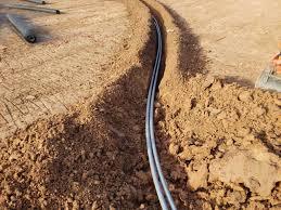
Direct laying of underground cables
Direct laying
This method requires digging a trench 1.5m deep and 0.45m wide, then covering it with a layer of sand. The cables are laid in trenches and covered with a 10cm thick layer of sand. To prevent mechanical damage, the trenches were then covered with bricks and other materials.
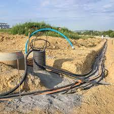
If more than one cable is required to be laid in a trench, a horizontal or vertical inter-axis spacing of 30 cm should be provided to prevent mutual heating.
This method is the most popular because it is simple and cheap. Cables laid using this method must use tar paper and burlap tape to prevent corrosion and electrolysis.

Advantage
Easier and cheaper than the other two methods
The heat generated in the cables can easily dissipate underground.
Cable traction laying method
Make sure areas and trenches where cables are to be pulled or laid are inspected and approved.
The drum must be placed on a pair of brackets and axles to allow for smooth pulling.
Laying cables into underground trenches
In order to move a cable drum or lay a cable, the direction of rotation must carefully follow the direction marked on the drum.
The winch should be carefully adjusted and secured securely to the required distance.
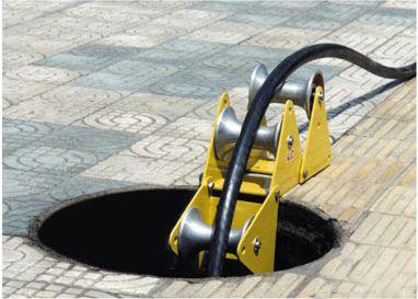
Cable rollers must be placed at maximum intervals of 2 meters as per specifications to prevent cable breakage during pulling operations.
The gap between the rollers must be constant and securely fastened.
Suitable angle rollers will be supplied upon request.

Extra care must be taken when driving into and through curves, crossing roads and existing pipes.
After checking the cable duct for debris and sharp edges, clean the duct if necessary.
If necessary, the cable should be treated with a sealant or draw compound to make it smooth and easy to pass through the cable duct.
Identification must be provided and both ends of severed cables must be sealed and taped.
Before splicing and backfilling are performed in accordance with specifications, sheath testing and bonding testing should be performed on laid cables.
The sheath test must be performed by applying a 10 kV DC voltage for one minute between the sheath and the outer graphite surface of the armor, with all other phases safely connected to earth, and the leakage current recorded on the sheath test sheet.

Click to learn more about our quality cable laying tools
Cable Connections and Terminations: Cable connections must be made with the best possible workmanship in accordance with the connection kit manufacturer's instructions or user's manual.
Trench backfilling and restoration
Along the cable route, the thermal resistance of the soil must be measured according to specifications.
According to code requirements, the thermal resistivity of the soil and the temperature of the backfill material must be measured.
As stipulated in the project specifications, the backfill material must be chemically neutral and have a maximum thermal resistivity of 120 cm2 C/W under operating conditions.
When the thermal resistance of natural soil exceeds 120 cm2 C/W, special cushion materials must be used according to engineering requirements.To maintain work continuity and progress, consultants, owners or clients can conduct inspections before installing caution tape, final backfill or cable route markings.
Need Duct Rodder for cable laying?
If there is any remaining excavation material, it must be leveled and distributed to restore the area to its pre-excavation condition, and excess earth may need to be dumped if necessary.
In tiled areas and walkways, permanent repairs are required.
Cable route markings:
For each circuit of the power cord, cable routing and connector markings must be provided.
Cable route signs must be set up at intervals of no more than 30 meters on straight lines, at cable route turns and at road intersections on both sides.
In order to identify seams, seam markers must be installed on top of the seams.
According to the authorized specifications, all cable runs and splice markings must be made of reinforced concrete and be of the truncated cone type.

Cable testing and commissioning
Conductor insulation resistance measurement and sheath testing
Notify interested parties so they can participate in testing if needed.
Verify that cable rating, type, size, and quantity comply with drawings and specifications.
The area surrounding the testing area must be fenced off and accessible only to authorized personnel.
Ensure that the testing site has up-to-date, calibrated testing equipment.
For safe handling and discharge of residual voltages, high-voltage gloves and a high-voltage earth rod must be provided.
By removing the graphite coating from a 500mm length of the cable, you can prepare both ends of the cable for testing.
Before cable testing can begin, a shortwave communications system must be in place.
An authorized representative is responsible for monitoring the non-test end of the cable to take safety precautions.
Cables must be checked for continuity and correct phase alignment.
The results of all required tests must be recorded in test format in accordance with local requirements.
A voltage of 10 kV must be applied between the sheath and the outer graphite surface of the armor for one minute with all other phases firmly connected to earth using a high voltage DC test kit and the leakage current recorded.
Residual voltages must be eliminated immediately after each phase test using a ground rod connected to earth.
Before connection, the insulation resistance between phase and ground must be measured.
Results must be recorded in accordance with the approved test format.
Search from here
Get Free Quotes
Scan the QR code and add my WeChat friends

Wechat : amxingda
Scan the QR code and add my QQ friends

QQ : 561****05


